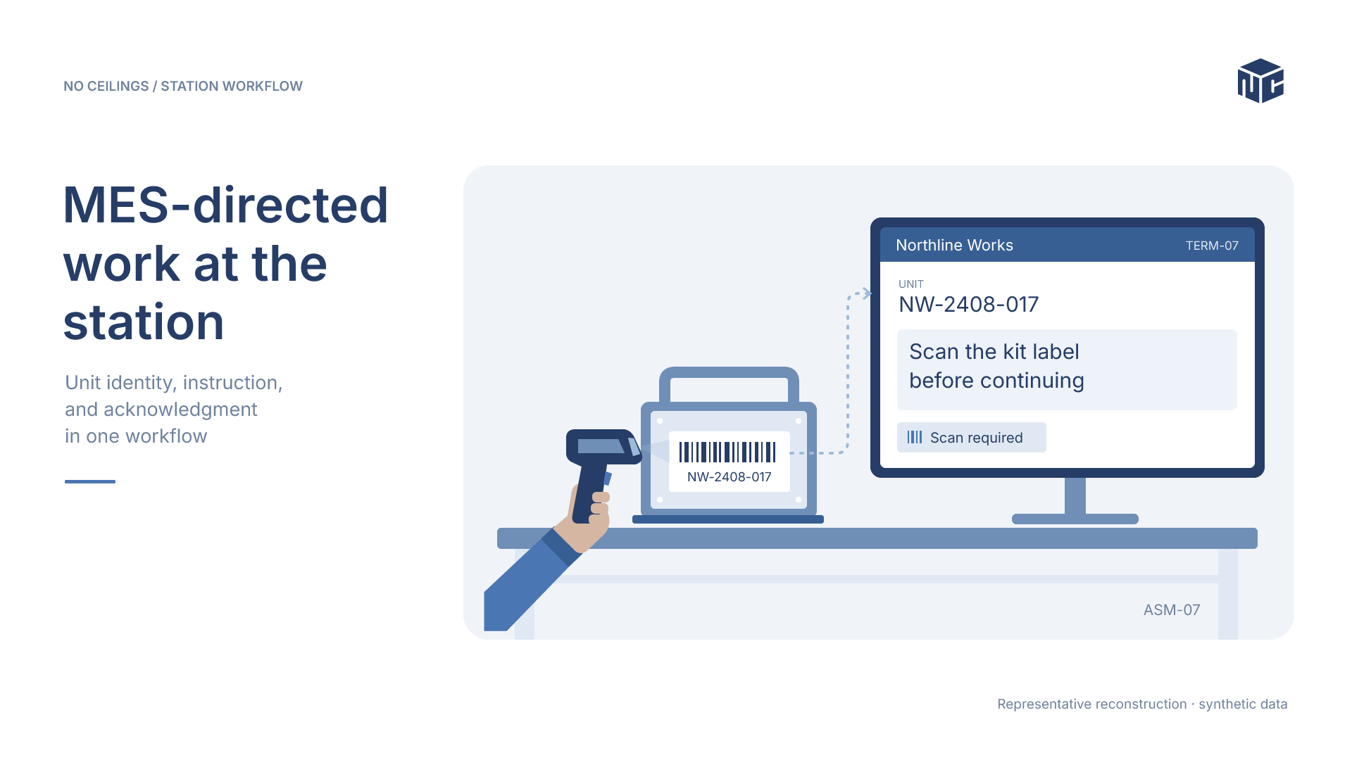
An assembly station must do more than recognize a serial number. It needs permission to begin, an instruction appropriate to the unit, a way to execute that instruction, and a reliable means of returning the result to the manufacturing execution system (MES). This case study examines how an Ignition station interface connected to SIMATIC IT through a MES integration service to coordinate those responsibilities.
The central design principle was to keep process direction in the MES while allowing Ignition to manage station execution and operator interaction.
The integration challenge
From unit identification to authorized work
A unit serial number and station terminal identify the work context. The MES determines whether work may begin and supplies the next action. Depending on the response, the station may display an electronic work instruction, validate a material scan, or coordinate an instrument. The next screen cannot simply be assumed from a locally hard-coded sequence.
Keeping three states aligned
The implementation had to reconcile the MES transaction, the operator-facing instruction, and the physical station. A result belongs to the specific action that produced it. Advancing the display without handling the corresponding transaction would leave the station and MES with different understandings of the work.
System architecture and responsibilities
The boundary between Ignition and SIMATIC IT
Ignition exchanged HTTP/XML messages with the MES integration service. That service provided the boundary to the MES message queue and mediated the acknowledgment exchange. Ignition did not independently define the manufacturing instruction sequence. It interpreted the returned action and coordinated execution at the station.
- MES: authorizes the unit and directs the next action.
- Integration service: mediates messages and acknowledgments.
- Ignition: manages station state, action handlers, operator presentation, and result submission.
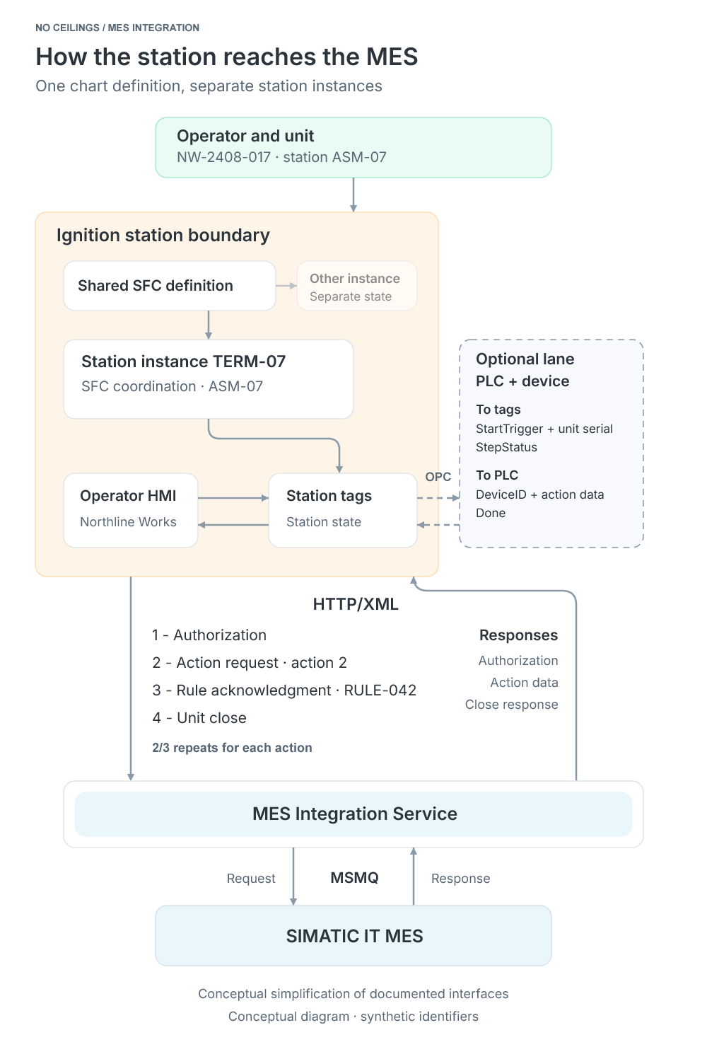
How the station reaches the MES
One chart definition, separate station instances.View Image
The transaction lifecycle
Four message roles
The protocol used four message roles. Authorization starts the interaction, action requests and acknowledgments repeat as work progresses, and a final exchange closes work on the unit.
| Message | Station purpose | What returns or advances |
|---|---|---|
| 1 | Request authorization for the identified unit | Permission to begin work |
| 2 | Request the next numbered action | Action type, rule ID, and action data |
| 3 | Acknowledge the returned action | Rule ID and any required result data |
| 4 | Close work on the unit | Unit completion exchange |
Action number versus rule ID
Message 2 requests an action using its sequence number. Message 3 acknowledges the rule ID returned with that action. The sequence position and rule identity are different fields and serve different purposes.
Keeping that distinction explicit ties scan values, instrument readings, or other result data to the action being acknowledged, even if its position in the instruction sequence changes.
A normal-path implementation sketch
The following Python-style pseudocode illustrates the transaction sequence. Its helper names are descriptive, not actual Ignition or MES integration service APIs.
authorization = request_authorization(terminal_id, unit_serial)
if not authorization.allowed:
    stop_station_work()
    return

action_number = 1
while True:
    response = request_action(terminal_id, unit_serial, action_number)
    if response.is_error:
        show_action_error(response)
        return
    if response.has_no_action:
        stop_station_work()
        return

    result = perform_station_action(response.action)
    acknowledge_rule(response.action.rule_id, result)
    if response.work_operation_complete:
        break
    action_number += 1

close_unit_work(terminal_id, unit_serial)
The action number advances only after a handled action. Authorization denial, error responses, and no-action responses take separate exits. The example deliberately omits retries, bypasses, timeouts, and station-specific recovery rules that are not established by the available material.
Orchestrating work inside Ignition
One SFC definition, separate station instances
An Ignition sequential function chart (SFC) coordinated the message sequence and station state. Each station configuration associated a terminal ID with a tag path, chart name, inhibit setting, and service address. A gateway timer checked the configuration every second and maintained the corresponding chart instances.
From start trigger to completion
An inspected chart example initialized station tags, waited for a start condition, processed Message 1 and Message 2, dispatched the returned action, sent Message 3, and eventually closed with Message 4 before releasing the station. Transitions also represented errors and operator controls.
The optional PLC-facing lane
A PLC-facing variant exchanged start triggers, action information, status, and a done signal through station tags and OPC. This was one supported coordination pattern, not a required feature of every workstation.
The operator experience
A shared interface with action-specific content
The documented HMI mapped each workstation to a terminal and used indirect tag bindings to read the relevant station state. A common operator shell selected content based on the current action type, allowing the interface to adapt without requiring a separate complete screen for every instruction.
Instructions, scans, and instruments
One supplied view paired electronic work instructions with a material-validation scan prompt. Other configured action containers covered acknowledgment, genealogy confirmation, instrument, join, and scan activities. Instrument actions could use device-specific templates for their inputs and outputs.
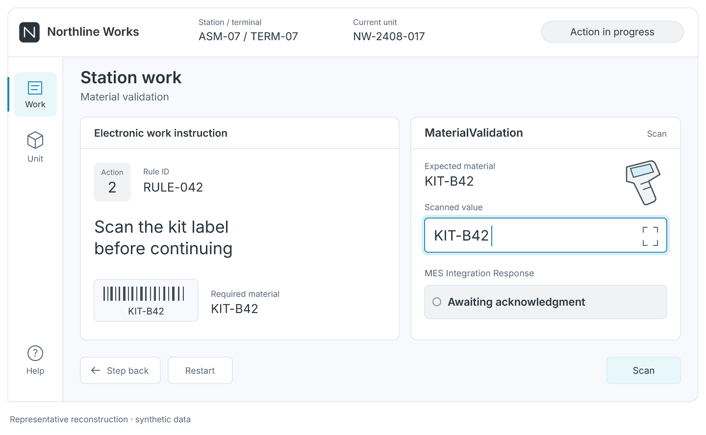
Station work and Material Validation
Reconstructed station view pairing an electronic instruction with the current scan action.View Image
The action type selected what the operator saw. The terminal mapping determined which station data populated that view.
Diagnostics and troubleshooting
Seeing both sides of the exchange
The diagnostic view exposed request and response areas for Messages 1 through 4, alongside station status and separate error fields. Engineers could compare the station’s current state with the messages it had sent and received when a workflow stopped progressing.
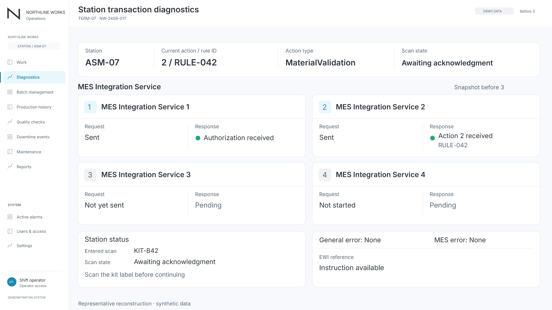
Station Transaction Diagnostics
Diagnostic view of message stages, station status, and error areas.View Image
Separating engineering detail from operator work
Keeping transaction diagnostics separate from the normal operator experience helped preserve a focused station interface while retaining visibility into the integration boundary. The documented view supports inspection of message stages and errors; it does not establish payload editing or measured reductions in troubleshooting time.
Engineering takeaways
Explicit ownership of each responsibility
The design assigned process authority to the MES, message mediation to the integration service, and station coordination and presentation to Ignition. The action number, rule ID, and returned result data provided distinct points of reference through the transaction.
Reusable logic without collapsing station identity
The combination of configurable SFC instances, indirect HMI bindings, and action-specific content offered a way to reuse application structure while retaining station-specific execution state.
What the record demonstrates
The available materials document configured chart instances, built operator and diagnostic interfaces, and the underlying transaction pattern. They do not establish a final commissioned station count, measured throughput improvement, or production-quality outcome. The engineering result shown here is the integration design and its visible implementation components.