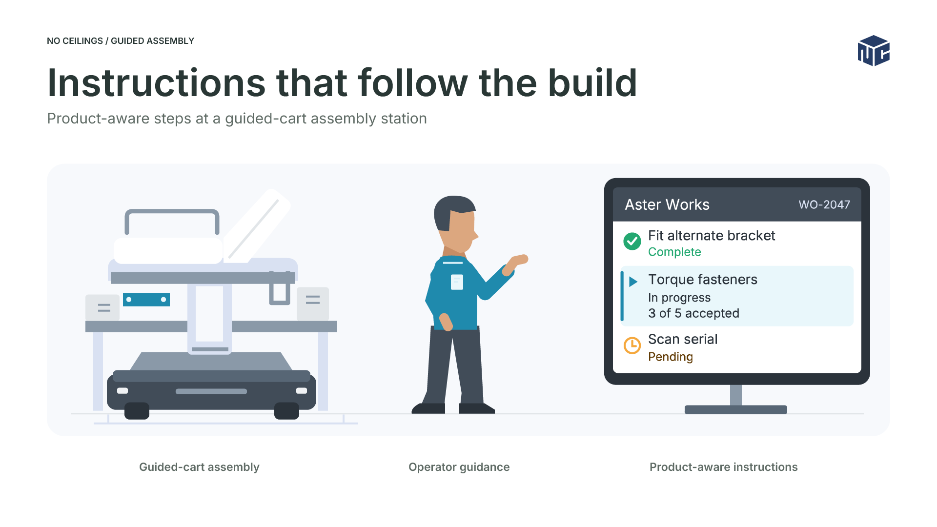
A medical equipment production program brought fabricated subassemblies into a main assembly line where a product traveled through multiple workstations on a guided cart for part of its route. The work at each station depended on the product, its order options, and the equipment available there. The instruction application was designed to turn that context into an ordered sequence an operator could follow, while giving engineering a way to configure instructions without changing PLC code for every station update.
The production setting
Different processes, one assembly context
Fabrication weld cells and the main assembly line had different control needs. Fabricated parts entered assembly, where operators needed the right work instructions at the right workstation. A static document would not express the same combination of product, order options, station assignment, and equipment feedback. The planned application represented work as configurable steps so an instruction could be assembled for the current production context.
Keeping movement control separate
The architecture assigned guided-cart location and movement to a dedicated cart controller. An assembly PLC handled the workstation control interface and remote I/O. Ignition supplied fixed operator clients, instruction context, and production data handling. The instruction interface could use shop-floor status, but cart movement and machine control remained with their respective control systems.
Cart presence and instruction selection served different purposes. Station and order context determined which work was relevant to the operator. The cart controller coordinated the vehicle.
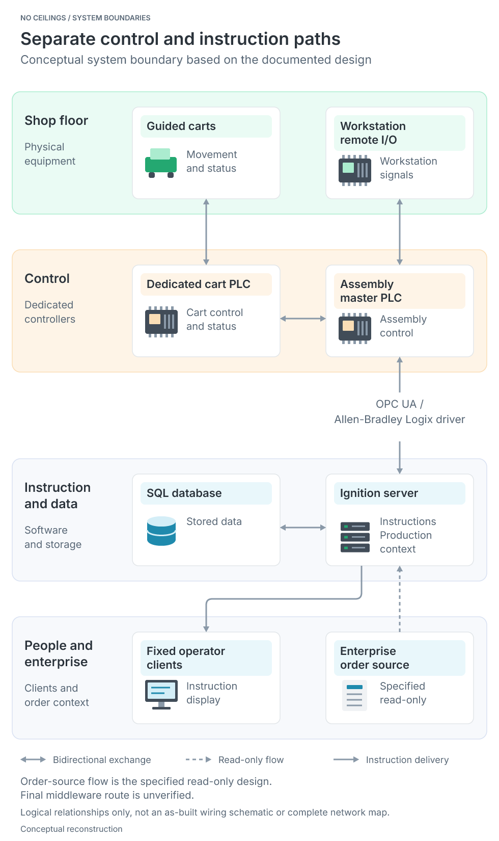
Separate control and instruction paths
The cart controller and assembly PLC handle movement and workstation signals while Ignition presents instructions and handles production context.View Image
How instructions were assembled
From production context to ordered steps
The application resources link products, work orders, equipment, instructions, ordered steps, and work in progress. The design called for step selection using the product and workstation context. Order options could further change which assigned steps applied. This let one stored instruction definition produce a relevant sequence for a particular build without treating every product variation as a separate, fixed document.
The following table is a synthetic example of the selection rule. The identifiers and options are fictional and illustrate how an option can include one step while excluding another.
| Assigned step | Option condition | OPT-B on order | Selected |
|---|---|---|---|
| Fit standard bracket | Include when OPT-B is absent | Yes | No |
| Fit alternate bracket | Include when OPT-B is present | Yes | Yes |
| Torque fasteners | Unconditional | Yes | Yes |
| Scan serial | Unconditional | Yes | Yes |
Python-style pseudocode below summarizes the option filter found in the project materials. It explains the decision, rather than reproducing executable Ignition code.
ordered_options = option_part_numbers_for(work_order)
selected_steps = []

for assignment in instruction.steps_in_sequence:
    option_present = assignment.part_number in ordered_options
    include = (assignment.remove and not option_present) or (
        not assignment.remove and option_present
    )
    if include or assignment.product_id is None:
        selected_steps.append(assignment.step)

return selected_steps
The filter keeps assigned steps in sequence. A step without a product association can remain in the list regardless of the option test. The real query also handles fields such as quantity and rework flags, so this example does not describe every runtime case.
An operator view built around the current step
The operator interface was designed to show serial and station context, an ordered step list, completed steps, a highlighted current step, and a related image. It supported both manual work and steps that waited for production equipment. That distinction matters at stations with a monitored torque tool: the screen could present the action, but equipment feedback determined when the configured step was complete.
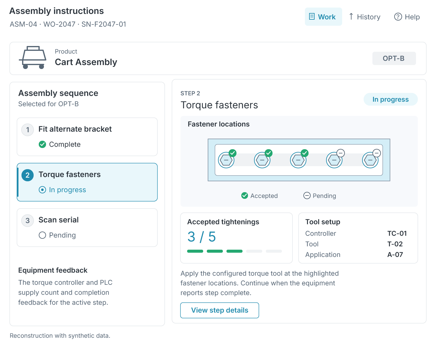
Assembly Work Instructions
Reconstructed operator view showing an active torque step with three of five acceptable tightenings reported.View Image
Equipment-aware progress and change management
A monitored torque step
For a torque step, the instruction configuration could identify the controller, tool, application, and required number of acceptable tightenings. The controller supplied the acceptable-result count, and PLC feedback exposed the current count and step-complete response. The application could display progress and retain the step until completion was reported.
The instruction specified the work and its required count. Controller and PLC feedback supplied the completion signal, so the on-screen sequence could reflect equipment progress instead of relying only on an operator button.
This Python-style pseudocode summarizes the documented command and response relationship. Its helper names describe the flow and are not platform APIs.
torque_command = {
    "controller": step.controller,
    "tool": step.tool,
    "application": step.application,
    "required_ok_count": step.quantity,
}
send_step_configuration_to_plc(torque_command)

def on_plc_feedback(feedback):
    show_accepted_count(feedback.actual_count, step.quantity)
    record_step_progress(feedback.actual_count)
    if feedback.step_done:
        complete_current_step()
The example uses the controller-reported accepted count and PLC step response. It does not assume that the instruction application evaluated raw torque values or retained every individual tightening result. Those details are outside the supported record.
Configuring and revising the sequence
The engineering workflow was designed to create and order steps, associate instructions with the relevant production context, and manage changes. Offline edits, restricted publishing, and version history were part of that design. Instruction records, version fields, and archive-related queries show that change management was addressed in the application.
An adaptable instruction layer
The application structure connected instruction and step records with station, cart, and work-in-progress data. It addressed the central engineering challenge: adapting the work shown to an operator while equipment feedback informed progress. The control boundary remained clear, with PLC systems responsible for cart and machine control.